|
Even before the development of true interstellar
spacecraft by various cultures, it was clear that directed-energy devices would be necessary to assist in clearing gas, dust,
and micrometeoroid material from vehicle flight paths. Emerging space-faring races are continuing to employ this method as
an excellent maximizer of shipboard energy budgets, because a relatively small energy expenditure produces a large result.
Material in space can be vaporized, ionized, and eliminated as a hazard to spaceflight. It did not take an enormous leap of
imagination, of course, to realize that directed energy could also prove to be an effective weapon system.
The lead defensive system maintained by Starfleet
Command for sublight use for the last century is the phaser, the common term for a complicated energy release process developed
to replace pure EM devices such as the laser, and particle beam accelerators. Phaser is something of a holdover acronym, PHASed
Energy Rectification, referring to the original process by which stored or supplied energy entering the phaser system was
converted to another form for release toward a target, without the need for an intermediate energy transformation. This remains
essentially true in the current phaser effect.
Phaser energy is released through the application
of the rapid nadion effect (RNE). Rapid nadions are short-lived subatomic particles possessing special properties related
to high-speed interactions within atomic nuclei. Among these properties is the ability to liberate and transfer strong nuclear
forces within a particular class of superconducting crystals known as fushigi-no-umi.
Shipboard phasers
As installed on the USS Cobain, the main ship’s
phasers are rated as Type X, the largest emitters available for starship use when Galaxy class starship was first designed.
Individual emitter segments are capable of directing 5.1 megawatts. By comparison, the small personal phasers issued to Starfleet
crew members are Type I and II, the latter being limited to 0.01MW. Certain large dedicated planetary defense emitters are
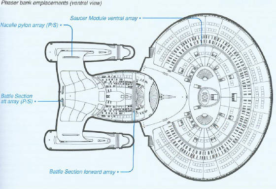
designated as Type X+, as their exact energy output remains classified. The USS Cobain supports twelve phaser arrays in two
sizes, located on both dorsal and ventral surfaces, as well as two arrays for lateral coverage.
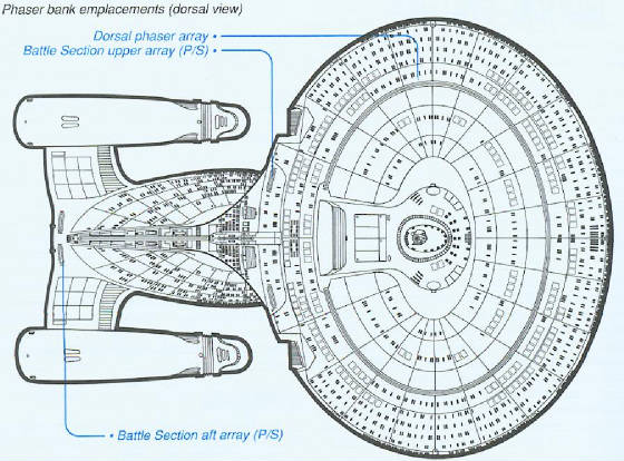
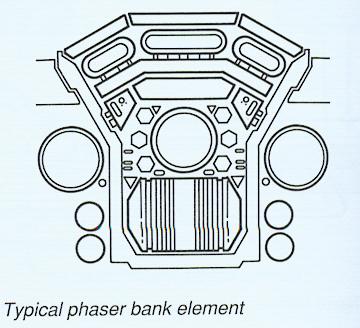
A typical large phaser array aboard the
USS Cobain, such as the upper dorsal array on the Saucer Module, consists of two hundred emitter segments in a dense linear
arrangement for optimal control of firing order, thermal effects, field halos, and target impact. Groups of emitters are supplied
by redundant sets of energy feeds from the primary trunks of the electro plasma system (EPS), and are similarly interconnected
by fire control, thermal management, and sensor lines. The visible hull surface configuration of the phaser is a long shallow
raised strip, the bulk of the hardware submerged within the vehicle frame.
In cross section (right), the phaser array takes on a thickened Y shape, capped with a trapezoidal mass of the actual
emitter crystal and phaser-transparent hull antierosion coatings. The base of an array segment sits within a structural honeycomb
channel of duranium 235 and supplied with supersonic regenerative LN2 cooling. The complete channel is thermally
isolated by eight hundred link struts to the tritanium vehicle frame.
The first stage of the array segment is the EPS
submaster flow regulator, the principal mechanism controlling phaser power levels for firing. The flow regulator leads into
the plasma distribution manifold (PDM), which branches into two hundred supply conduits to an equal number of prefire chambers.
The final stage of the system is the phaser emitter crystal.
Activation Sequence
Upon receiving the command to fire, the EPS submaster
flow regulator manages the energetic plasma powering the phaser array through a series of physical irises and magnetic switching
gates. Iris response is 0.01 seconds and is used for gross adjustments in plasma distribution; magnetic gate response is 0.0003
seconds and is employed for rapid fine-tuning of plasma routing within small sections of an array. Normal control of all irises
and gates is affected through the autonomic side of the phaser function command processor, coordinated with the Threat assessment/tracking/targeting
system (TA/T/TS). The regulator is manufactured from combined-crystal sonodanite, solenogyn, and rabium tritonide, and lined
with a 1.2 cm layer of paranygen animide to provide structural protection.
Energy is conveyed from each flow regulator to
the PDM, a secondary computer-controlled valving device at the head end of each prefire chamber. The manifold is a single
crystal boronite solid, and is machined by phaser cutters. The prefire chamber is a sphere of LiCu 518 reinforced with wound
hafnium tritonide, which is gamma-welded. It is within the prefire chamber that energy from the plasma undergoes the handoff
and initial EM spectrum shift associated with the rapid nadion effect (RNE). The energy is confined for between 0.05 and 1.3
nanoseconds by a collapsible charge barrier before passing to the LiCu 518 emitter for discharge. The action of raising and
collapsing the charged barrier forms the required pulse for the RNE. The power level commanded by the system or voluntarily
set by the responsible officer determines the relative proportion of protonic charge that will be created and pulse frequency
in the final emitter stage.
Beam Emission
The trifaceted crystal that constitutes the final
discharge stage is formed from LiCu 518 and measures 3.25 x 2.45 x 1.25 meters for a single segment. The crystal lattice formula
used in the forced-matrix process is Li><Cu>>:Si::Fe>:>:O. The collimated energy beam exits one or more
of the facets, depending on which prefire chambers are being pumped with plasma. The segment firing order, as controlled by
the phaser function command processor, together with facet discharge direction, determines the final beam vector.
Energy from all discharge segments passes directionally
over neighboring segments due to force coupling, converging on the release point, where the beam will emerge and travel at
c to the target. Narrow beams are created by rapid segment order firing; wider fan or cone beams result form slower firing
rates. Wide beams are, of course, prone to marked power loss per unit area covered.
|